Who was that masked material?
Masking is the process of hiding and revealing portions of a pattern using the luminance values of another pattern or map. The concept is simple, as is the fundamental application, but by using masking upon masking you are able to generate very complex materials that are convincing to the viewer.
This column will introduce you to the process of masking at both the map and the material level in 3ds max or Autodesk VIZ, both programs share the same capabilities. We will start with the simple applications to see how masking functions, then work into more complex examples including animated masks.
Grayscale images generally function best as masks. It is the Luminance value of a pixel that controls the masking effect, white is opaque…black is transparent…levels of gray are somewhere in-between. Color images may be used as masks, but it is very difficult for most of us to judge a particular luminance value of a color. For example, green and yellow look very different, but might have the same luminance values and would be ineffective as a mask.
As with all topics in max or VIZ it is best to start simply to get a feel for the functionality and controls, then work into more complex applications. I will include a VIZ 4 file for downloading that can be opened in either VIZ 4 or 3ds max 4 and 5. For those of you with previous versions of max or VIZ the descriptions should be enough for you to build your own similar scenes and examples.
Where can masks be applied?
Masking can occur at either the map or the material level. If masks are applied at the map level the effect is only for that particular material component; Diffuse Color, Opacity, Reflections, etc. The material masking allows all components of materials to be hidden or revealed by the mask.
Two examples of masking at map level would be the Mask map that allows one map and one mask that allows the underlying Diffuse Color to show through and the Mix map that allows two maps with an optional mask. Another map type called Composite can be used for masking effects that use image Alpha Channels that will act as the masking agent. Alpha Channels will be discussed later in the column.
At the material level my favorite is the Blend material that allows two materials with a mask. This allows you to reveal two separate complete materials with different color, bumps, reflections, for example, with the mask.
The depth of masking is unlimited, for example you can have a mask map within a mask map within a mask map or a Blend material made of a material plus another Blend material, each with it’s own mask. Like I said earlier, though, start simply and build on your knowledge as you become comfortable with the process.
Masking at map level
As mentioned, there are several methods for applying masks at the map level of a material and the one we’ll look at here will be the Mask map.
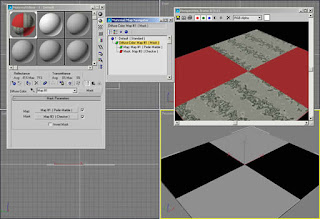
The scenario is a tile floor with solid red tiles alternating with marble pattern tiles and can be accessed by downloading Tile_viz4.max. (Download zip file at end of article) The red color will be set as the Diffuse and Ambient Color swatches of the material. A Mask map is applied to the Diffuse Color slot and is composed of a Perlin Marble map and a Checker mask. The white areas of the Checker mask are opaque and show the marble map. The black areas of the Checker mask are transparent and reveal the underlying solid red Diffuse Color. See Figure 1.
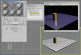
This example shows how the process works in a Diffuse Color example. In the next example I use a Mask map in conjunction with a Raytrace reflection map on a tile floor that can be found in Wall_viz4.max. The scenario here is a ceramic tile floor with Brick maps defining the color and the bump pattern and a Raytrace map that causes the material to reflect its surroundings.
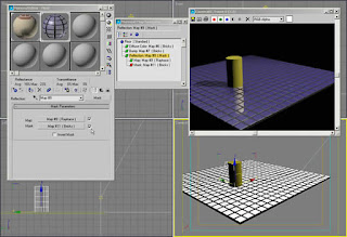
In the Mask map of the Reflection slot I have disabled the Bricks mask by unchecking it in the Mask Parameters rollout causing the reflection to be the same for both the tiles and grout. See Figure 2.
By applying the same Brick map I used in the Bump slot of the material to a Mask map with a Raytrace map, the reflections only occur in the white areas of the mask. See Figure 3
Masking at the material component level offers a lot of possibilities for experimentation. The same Reflection masking as above could be used with Raytrace and a Noise mask to give the illusions of puddles on a road surface. A combination of Bricks map in the Bump slot with a Gradient Ramp mask could create the illusion of a knurled surface on a tool handle. Use your imagination and experiment.
Masking at the material level
Masking at the material level functions the same as at the map level but increases the control another notch. Each material can have widely varying attributes like color, shininess, and bumps, each revealed or hidden by the mask. In the example here I’ll use the Blend material with the optional mask.
The scenario will be a wall that needs a combination of brick and stucco. As in most projects the exact material placement will be held in secret by the designer right up to the last minute of the deadline. I want to be able to make last minute changes quickly and easily. This is also using the file Wall_viz4.max. (Download zip file at end of article)
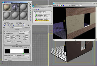
Blend material with masking allows us to do this nicely. I create the Blend material with a Brick and a Stucco material, each with different patterns, colors, and bumps. I’ll use a Gradient Ramp mask that has been adjusted for solid bands of black and white to reveal the two materials exactly where I want them on the model.
This wall example also illustrates a powerful feature of max and VIZ called Map Channels. Because the patterns of the brick, the stucco, and the mask repeat differently over the wall surface I needed different mapping coordinates for each map. The wall has three UVW Map modifiers each set to a different Map Channel. The Gradient Ramp mask is set to use Map Channel 1, the Brick map uses Map Channel 2, and the Stucco map uses Map Channel 3 so that each pattern may be adjusted independently. The Map Channel in the UVW Map must match the Explicit Map Channel setting of the map in the Material Editor.
The Gradient Ramp map has been rotated in the W axis in the Coordinates rollout for proper orientation on the wall. An alternative would be to rotate the UVW Map modifier Gizmo.
Figure 4 shows the Gradient Ramp map and the rendered image shows the result of the masking. Each material has it’s own color and bump information.
This same wall material could have been used with a Noise map to simulate a stucco wall with sections of plaster fallen off to reveal bricks below. You could also create the illusion of rust coming through a metal panel or grassy areas with patches of rock and dirt.
Animated masks
Masks do not have to be static images or maps. Interesting effects can be created by using animated masks in the form of avi or mov files or as sequentially number still images. You might say that it sounds logical, but you don’t have a 2D animation program to create the animated maps. Don’t fear, it is easy to create animated masks in 3ds max or Autodesk VIZ.
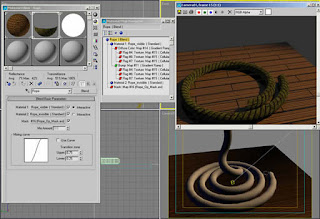
In the file called Rope_viz4.max (Download zip file at end of article) is a section of coiled rope made by lofting a circle around a helix and applying a material to it. The task at hand is to make the rope disappear over time, not all at once, but from one end to the other.
The solution here is to use a Blend material and a mask again. In the Blend material is a rope material and a material that is completely invisible. The opacity and glossiness of the material have been set to 0. It is important to set the glossiness to 0 to avoid a highlight on the invisible portion of the rope.
The mask is created in VIZ 4 by assigning a pure white material to a flat plane and animating the plane moving from just off screen to filling the viewport of a camera view. In this case it is Camera02. The animation was rendered as an avi file and used in the Mask slot of the Blend material.
Figure 6 shows the Blend material level in Material Editor and the result of rendering frame 15 of 30 frames. Half the rope that you see in the Camera01 viewport is invisible in the rendered image. See Figure 6.
The same technique could have been used to reveal a shiny new material under an old crusty material over time or to make a surface appear to bubble from the heat by revealing the base material with same material with a bump map added.
Note that it is important in this case that the rope be created in max or VIZ by lofting. Lofted objects are the only objects that generate mapping coordinates that allow the patterns to follow the curvature of the objects. For example the rope material and the mask both follow the rope as it winds upward.
Alpha channel and masking
You will often hear the term Alpha Channel in conjunction with maps in max or VIZ. It refers to information that is stored in certain bitmaps that determine transparency. The most popular files types with alpha channels are tga, tif, and png.
Computer generated images are displayed in pixels, either on screen or when printed. Since the early days of computer graphics anti-aliasing has been used to smooth diagonal lines and edges caused by stair-stepping across squarish pixels.
Anti-aliasing is done by blending the pixels at the edges of contrasting colors to make the edge appear smoother. If a red diagonal line is applied to a yellow background then some pixels are quite red with a little yellow, some are half red, half yellow, and others are quite yellow with a little red. This smooths the transition when seen from a distance.
However, if the red line is lifted from the yellow background and composited onto a blue background the yellow remnants look terrible and are worse than no anti-aliasing. 32 bit files or files with 24 bits of color and 8 bits of alpha channel use transparency pixels instead of the background color to create the anti-aliasing effect. Now when the red line with varying transparent pixels are composited to another background there is no problem and everything has clean edges that appear smooth.
Max and VIZ both can take advantage of files with Alpha Channel in the masks for a cleaner blend at either the map or the material level. Workings on the examples in this column don’t require Alpha Channel to work, but keep it in mind if you are experiencing problems with detailed masks in your explorations.
Summary
Masking gives you control of materials you never thought possible. The concept and application are simple at its base level, but by combining masks at different levels you can create materials that are complex yet easily edited.
As a personal plug, if you are a 3ds max 5 user, my new 3ds max 5 Fundamentals book by New Riders Publishing is set to appear in late October or early November. It is somewhat different than my previous fundamentals book in that I focus on the many new max 5 features in a series of exercises that take you from a medieval village to building a personal transporter, and a trip to the fortune tellers. The exercises are designed to be an interesting and informative way to learn uses for max 5 features from modeling, to materials and radiosity lighting, to collision detection and scene editing and compositing.
In any case, good luck and have fun.
Ted


No comments:
Post a Comment