Photobucket

related link

Saturday, February 2, 2008

LOFTING 3

Ted Boardman tedb@tbmax.com http://www.tbmax.com


Well, it really looks as if summer is not going to make it to New England. Small low-pressure weather systems have been spiraling up the east coast bringing a steady northeasterly wind off ocean water that is still around 55 degrees F. It’s cloudy, it’s rainy, and it’s downright cold on the coast.

The cool, cloudy weather is good for the flora. A recent ride up through the mid Maine coast area was a trip through beautiful meadows of wild flowers, especially the native purple and pink Lupine, and the rocky hillsides devoid of trees and covered with low blueberry bushes.


Abnormally cold and rainy weather certainly makes people more inventive and adventuresome when it comes to weekend activities that, of course, bring me to my column topic for this month. Try being a little more inventive and adventuresome in your use of some of the tools available in max and VIZ.

This month we will look at one possible solution to a problem that came up on in the VIZ forum recently. It will illustrate an unusual modification to lofting that I seldom see anyone use but one that really adds lots of flexibility to an already powerful tool.

The point of this column is not to show you how to create cabinet doors. The doors are simply an example to make you aware of a lofting option that can prove very powerful. Keep the trick in mind and you will find uses for it in your work.

The Problem

A cabinet door needed to be visualized with a wood grain finish. The door’s vertical styles and horizontal rails had profiles on the inside and outside edges and the joint was to be a mortise and tenon butt joint.

One person in the forum showed a great example of using Boolean operations as a solution to the problem. 3D Boolean operations have several disadvantages in max and VIZ, however. They often fail, they are memory intensive, and they tend to create long thin faces that will potentially create problems with lighting and shadows. Also, changes will require you redo all the Boolean operations.

I suggested lofting. But as we’ll see the lofting requires a few simple but obscure modifications to be effective and offer modeling flexibility.

The wood grain material had to be mapped to correctly reflect the joint conditions as the cabinet doors will be viewed closely, otherwise a straight loft along would be sufficient for most cases, especially if the corners had miter joints. See Figure 1.


Figure 1: Perspective viewport showing cabinet door shape lofted around a path. A simple wood grain map is shown in the viewport.


Tip: Lofting generates mapping coordinates that allows the map to follow the curvature of the path. This is often a good reason in itself to choose lofting over other creation methods.

Lofting the stiles and rails separately is a beginning to the solution, but as you see in Figure 2 just butting them does not come close to giving a clean joint or acceptable end condition for either the stile or the rail.


Figure 2: Lofting the rail and stile as separate objects and butting does not offer a solution.


Extending the horizontal rail into the vertical stile until the top grain surfaces are in the correct position does give a clean inside miter joint of the molding and correct representation of the wood grain. See Figure 3.


Figure 3: Extending the rail into the stile cleans the inside corner and gives a proper appearance for the topmost wood grain surfaces


There are two issues with the end condition of the vertical stile that I want to address with this column. First, it must be adjusted to add the molding profile rather than just to end abruptly in space. As you will see this can be accomplished with multiple loft shapes on the same path.

Next is the representation of a tenon on the end of the rail that extends into the stile. It could be created just by adding a box to the end of the lofted rail the size of the tenon. Any changes to the width of the rails and stiles would require an adjustment to the size and position of each box at the corners of each door. An easy enough task if you only have a few, but if you have many similar objects it quickly becomes a management nightmare.

A Tip that offers a Solution

The key to this lofting tip revolves around the ability to modify 2D shapes in the third dimension to affect a change on the end conditions of the lofted object. In Figure 4, I have extended the rail to the center of the stile. This causes a bad condition with coincident faces where the computer doesn’t know which faces you want to view. Renderings will unpredictably display one or the other and you have no control over which of the coincident faces show.


Figure 4: Coincident faces are a bad situation in max and VIZ over which you have no control to view one or the other causing problems with materials and shading.

The trick here, as I mentioned, will be to manipulate the 2D shape in the third dimension to make a “step” at the end of the loft object

Figure 5 shows the 2D shape used for the horizontal rail profile in sub-object Vertex mode.


Figure 5: Original rail 2D shape in sub-object Vertex mode.


I am going to use the Refine command to add two new vertices near the bottom of the short vertical sides at the top of the shape. See Figure 6


Figure 6: At sub-object Vertex level, use Refine to add two vertices to the short vertical edges at the top of the shape


In the Front viewport I select the topmost four vertices of the shape. I toggle the Transform Type-in to Offset mode at the bottom of the display. I then enter 2” in the Z axis field and hit Enter. This moves the four selected vertices back to match the top surface of the vertical stile. See Figure 7.


Figure 7: By moving the vertices of the 2D shape in the Z axis, a notch is created at the end of the loft object. The Perspective viewport has the stile’s Properties set to See-Thru and the Left viewport shows the displacement of the vertices in the Z axis


Note: in this example I am using only one shape on the loft path to define the 3D object so I can illustrate the effect. The opposite end of the loft object has an overhang that corresponds to the notch on the end you see in Figure 7. You would need two loft shapes, one at each end of the path, with the vertices moved the positive or negative Z axis to get a notch on each end.

Figure 8 shows a couple of quick examples of using the same technique to create objects that might be difficult to create with the same flexibility with other modeling methods. The beauty is that any changes to the 2D shape or path will be parametrically reflected in the 3D object. The object on the right has a Bend modifier on each shape the offers another level of editing capability.


Figure 8: Two more quick examples of 2D shapes modified in the third dimension to create complex, easily edited 3D geometry.


The End

No, this is not the end of the column, just the end of the vertical stile. It should be milled to have the same profile as the edge of the outside edge of the horizontal rail.

Note: if you refer back to Figure 5, you will notice that the quarter-round is not made of arcs but three straight Segments. By itself this amount of detail will usually show up as faceted surfaces in the 3D mesh when rendered. In the Skin Parameters of the 3D mesh objects I have also set the Path and Shape Steps to 0. This insures that the frames are made with a minimal number of faces for greater efficiency. These are details that can easily make a big difference in productivity. We will remove the faceting in the mesh by applying a Smooth modifier at the end of the exercise.

If you look at Figure 9 you will see several 2D shapes similar the original 2D profile at the top. Each subsequent shape has it’s upper vertices moved downward to match the height of the corresponding point on the profile.


Figure 9: Starting with the original shape at the top, each clone has it’s upper vertices moved downward to match the height of the profile itself.


These 2D shapes will be inserted at various percentages on the loft path to create a stepped end to match the profile.

In the Modify panel, Path Parameters rollout, I adjust the path percentage to be at the edge of the first profile drop. In this example it is at 97.1 percent. See Figure 10


Figure 10: Loft object’s Path setting is at 97.1 percent. The yellow indicator is at the edge of the profile cut.


At this point, I Get Shape and pick the original shape. This holds the original shape to this point on the loft.

I then set the Path setting to 97.15 and get the next shape to create an almost perpendicular drop to the top of the quarter-round. See Figure 11


Figure 11: Put the next 2D shape at 97.15 percentage along the path to create a drop at the top surface of the vertical stile.


At 98.1 percent I get the third shape, at 98.7 the fourth shape, and at 99.1 I get the last shape.

Finally, I apply a Smooth modifier to each loft object with AutoSmooth checked on and the Threshold set to 50 degrees for this example to smooth all faceting.

There is more work that could be done with the materials, but this default Wood is sufficient to see the effect. See Figure 12.


Figure 12: Rendered image of the finished rail and stile


Summary

Hopefully, this simple exercise will give you some insight into the capabilities and power of some lofting options that are not often used. The advantages are the ability to make quick changes to the 2D shapes used as loft paths and cross-sections shapes to radically change the cabinet doors.

It you create a typical door and clone it throughout the scene as Instance clones then the 2D shapes will still affect all Instances.

Experiment with the technique on simple objects to become familiar with the process and it will become a useful tool in your repertoire to create efficient and easily edited objects to increase your productivity.

The example files have been created in 3ds max 4.

Good luck and have fun.

Ted


Read More......

Friday, February 1, 2008

MATERIAL LIBRARIES

Ted Boardman tedb@tbmax.com http://www.tbmax.com

Siggraph 2002

I’d like to thank Jeff Mottle for hosting a great get-together for the cgarchitect participants of Siggraph 2002. Frankly, I was a little surprised there are so many architects at Siggraph, especially with the economy lagging these days. Siggraph is heavily skewed toward the film and television crowd with a fair amount of computer gaming thrown in.

When you think about it though, many of you entered into architecture to create spaces and worlds for people to exist in. That’s pretty much what movies and games are all about even though it may be for entirely different reasons. Both areas of visualization have lots that they can learn from each other. For example, the movie industry could learn more about space and scale in the fantasy worlds they create within the computer and architects could learn about storyboarding and pre-planning that would allow much move efficient scenes that contain only what the client needs to see.


If I had to choose a common technical theme throughout my conversations it would seem that better control of shadows and reflections were high on many of your lists. Also better methods of creating immersive environments for your clients to wander freely about in, while retaining high quality lights and materials was mentioned in several conversations.

The software industry is making great strides in that direction and hardware is almost a non-issue with all the powerful systems being offered at reasonable prices.

It was great to see some old acquaintances and to meet some new ones and to hear impressions of what is happening with visualization in the architectural fields. I really want to thank those of you who didn’t make it to the reception, but did stop me on the show floor to introduce yourselves and let me know that you read this column.

Hope to see more of you next year in San Diego.

Now Where Did I Put That?

A question that is posted quite often on the various VIZ and max support forums is “why can’t I have more than 24 materials?” so I thought I would ramble through some of the tools and concepts available for storing and locating materials while covering some more general materials issues along the way. Keeping track of your materials will increase productivity by reducing the amount of time you spend searching for and recreating materials.

There are essentially three places that materials can be stored in either 3ds max or Autodesk VIZ:

• Material Editor – materials can be kept in the 24 Material Editor sample windows
• Scene – materials can be applied to, and retrieved from, objects in the scene.
• Material Library – materials can be stored in a separate file with the .mat file ending

Material Editor: The First Choice

Very often you will be creating your materials from scratch in the Material Editor, as a matter of fact, I tend to recommend it, even though the learning curve seems steep at first.

Use the materials that ship with the software and materials that you may get from other sources as guides to creating your own materials. The materials in your scene will be the primary component of visualization that defines your style and acts as your signature to distinguish your work from others. Take the time to learn the ins and out of the Material Editor and how the materials you create interact with light to make your images stand out. There is nothing more discouraging than to go into a presentation or job interview and have your scenes looking similar to the last applicant because all the materials are “out of the box”.

When you open the Material Editor you are presented with six sample windows with spheres that show a representation of the materials you are creating. I say representation because of the lighting and the fact that it is a sample sphere by default. Scene lighting affects the look of your material profoundly. You will often get a great looking material on the sample sphere that is just plain embarrassing when rendered. Two things are the cause of this, the lighting and the shape of the surface. The shape of surfaces is especially important for materials with reflections and specular highlights as each play very differently over a flat or curved surface.

TIP: If you create an object that is about 100x100x100 units and save it to a file, (optionally with lights, camera, and mapping coordinates), you can it in any sample window in place of the default sphere. See Figure 1 for a lofted object that has a combination of flat and curved surfaces. In the Material Editor, go to Options, Custom Sample Objects and load the file. Then in the Material Editor, click the Sample Type button and you will have a new flyout button that will call the new sample object. To better see the results of any reflections in the material you can also turn on the Background toggle to see a checkered background in the sample window.


Figure 1: A Custom Sample Object used in the Material Editor for more accurate material rendition.


Note: Radiosity and Light Tracer rendering effects are never seen in the Material Editor

See why I said I’d ramble…when you create a material in the Material Editor and save the file the material remains in the editor and will be there when you open the file again. However, if you create a material in the Material Editor and quit or reset without saving the material is lost forever.
Scene Materials: A Better Choice

When you create materials in the Material Editor and assign them to objects in the scene the materials are, of course, saved with the file. Even if you clear the Material Editor, as long as a material is assigned to an object it is not deleted from the scene.

Let’s assume you have created one material and assigned it to an object in the scene. By the way, you can tell that a material has been assigned to an object in the scene by the triangles in the corners of the sample window. These triangles indicate a “hot” material; when you change the material in the Material Editor it will automatically update in the scene.

For whatever reason, you then drag one of the default sample windows on top of your hot material sample window. Your material disappears along with the triangles in the sample window. The material is still on the object in the scene even though it is not in the Material Editor any longer.

But, you were not really finished editing that material and now it’s gone and you can’t make any changes! No, that’s not the case at all. You can retrieve materials from objects in the scene and place them back in the Material Editor by using the eyedropper button (Pick Material from Object) just to the left of the material name field and picking the object in any viewport.

Note: if you replace a material in a sample window that hasn’t been assigned to an object in the scene, you will lose that material.

TIP: if you double-click on a sample window, you can magnify the window for better viewing. You can also rotate the sample by holding the mouse wheel down and moving the cursor over the original sample window (not the magnified one) or you can right click on the sample window and use Drag/Rotate.

Material Libraries: The Best, Hands Down Choice

The best method of dealing with materials is to use Material Libraries. These are specific files with the .mat ending that store the descriptions of your materials. The biggest advantage of storing materials in libraries is that the materials will be available from any scene and by all users in your company. It is a good habit to put your material in a library as soon as you create it.

The process goes like this the first time around:

1. You create a material in the Material Editor and click the Get Material button to call the Material/Map Browser. By default this show you a list of new material types (blue spheres) and map types (green or red parallelograms). See Figure 2.


Figure 2: The default Material/Map Browser shows material and map types


Note: the red parallelograms indicate Show Map in Viewport is active for that map.

2. In the Browser, check the Browse From: Mtl Library radio button and you get a list of material and maps in the current library, which by default is 3dsmax.mat or 3dsviz.mat.

3. At the top right of the Browser, click the Clear Material Library button. This is non-destructive! It only clears the list and does nothing to the .mat file on disk.

4. Drag and drop your material from the sample window to the Browser.

5. In the Browser, click File:Save As and choose a sub-directory and filename that is appropriate.

Material Libraries may be opened from any scene and the material can be dragged from the library to any sample window in Material Editor or directly onto objects in the scene.

TIP: if you have Microsoft Access on your machine when you install max or VIZ the Windows file association may be set to .mat files from Access. Changing the Windows file association to max or VIZ will allow you to use the library files but will not harm Access in any way.

Set your Material Libraries up in logical groupings that make sense for your production environment. The material descriptions do no take up much disk space and can be duplicated in many different libraries. For example, you should have a Material Library that contains all the materials for each project, but you can also have libraries that contain all stone materials or sky materials, or a library that contains high-resolution materials. Each of those libraries may contain some of the same material descriptions.

Accessing Materials in a Scene

You now know that materials may be stored in a scene, but there are several areas of a scene from which you can view those materials by choosing from the Browse From options. You can browse from:

• Material Library – an open library file
• Mtl Editor – the 24 material sample windows
• Active Slot – only the selected sample window in Material Editor
• Selected – materials on the selected objects in the scene
• Scene – all materials assigned to objects in the scene
• New – the default listing of all material and map types used to create new materials

The Material/Map Browser also has an option in the File area to merge Material Libraries into the current library. This would allow you to make all wood materials available in the current project file, for example.

Summary

So, the answer to the original question is that you are not limited to only 24 materials. For all practical purposes there is no limit to the number of materials, only that you may only view and edit a maximum of 24 at any one time. In addition you could have 24 complex materials like Multi/Sub-Object or Blend materials that have multiple levels of blending in the Material Editor at any one time. Each sub-material could be dragged and drop individually onto objects in the scene.

There is plenty of flexibility in the system and it essentially becomes a management issue to coordinate all users to be familiar with library structure and to have policies in place to keep from overwriting or recreating existing materials.

Take the time to investigate the options available in the Material Editor so you can quickly create and edit your materials for knockout presentations that give you the edge over your competition.

Have fun and good luck.


Read More......

Thursday, January 31, 2008

LOFTING 2

Ted Boardman tedb@tbmax.com http://www.tbmax.com

Fundamental Lofting Methods: Part II

Last month we had a look at the fundamentals of lofting a shape along a path in either Autodesk VIZ or 3ds max. In one of the exercises you lofted a rectangle along a path to create a small section of sidewalk, you then edited the path to fillet the corner resulting in a curved portion. Finally you optimized the mesh by changing Path and Shape Steps and by adding vertices to the curved segment of the path for more local detail.

This month we will investigate lofting a little deeper. You will learn how to apply a handicap ramp to the sidewalk by lofting multiple shapes along the same path. Remember there is no limitation to the number of shapes on any given path or the number of vertices in each shape. However, each shape must have the same number of spines, for example you cannot loft a Donut shape (two splines) and a Circle shape (one spline) on the same path.


Figure 1: A rectangle lofted on a curved path to create a sidewalk


In Figure 1 you will see the rectangle used last month to loft the curved sidewalk. The result is a rectangular cross-section along the entire walk.

There is a copy of the original rectangle that has been edited by adding a vertex and moving one corner to create a sloped section.

HINT: I’ve set the initial file up with a little glitch that will illustrate something that occurs quite often in lofting production and is one of the leading causes of users abandoning lofting as a tool in max or VIZ. Can you guess where there is a problem by looking at the shapes? I also selected the shapes and, in the Object Properties dialog, set Vertex Ticks on so you can see the shape’s vertices without being in sub-object Vertex mode.

Lofting Multiple Shapes on a Path

The process involved in lofting multiple shapes on a path is to simply go to a different level on the path and perform the Get Shape operation again. If you select a loft object and go to the Modify panel, there is a rollout called Path Parameters. See Figure 2.


Figure 2: In the Modify panel of a selected loft object you will find Path Parameters rollout.


It is set to 0 percent along the path as being the active level of the loft object. This is measured from the First Vertex of the loft path. There are options to measure the distance in display units Distance and Path Steps. In this case we have Path Steps set to 0 for optimization of the mesh, so each Path Step is a vertex along the path.

TIP: To find the length of a shape, select the shape, go to Utilities panel, and choose Measure. Using Measure on 3D objects will report surface area and volume.


Figure 3: Changing the Path, Distance setting for the loft object moves the yellow tick from First Vertex to, in this case, 12’0” down the path.


In this example we will use Distance to determine the active level on the path. The number display in the Path field is now in feet and inches rather than in percent. If I enter 12’0” in the Path field a yellow tick on the path moves 12 feet along the path and that becomes the active level. See Figure 3.

Figure 3: Changing the Path, Distance setting for the loft object moves the yellow tick from First Vertex to, in this case, 12’0” down the path.


In Modify panel I pick Get Shape and pick the new cross-section shape to set it at this level. The result, however, might not be exactly what you expect, let alone what you want. See Figure 4.


Figure 4: Get Shape at the 12’0” level creates a nasty twist to the sidewalk.


The twist is caused by the First Vertex position on the shapes. The First Vertex shows up as a box on a vertex in the viewport and, as you can see, they are not in the same relative position on each shape. (This is the glitch I introduced to illustrate a point). The lofting process analyzes the shapes on the path and connects the First Vertex of each shape, then it creates a new segment for each vertex and Shape Step setting, resulting in a 3D mesh.

To correct the problem I will select the sloped shape and go to Modify panel, sub-object Vertex. I select the upper right vertex and click the Make First button. Making the First Vertex on each shape in the same relative position takes the twist out of the loft. But it still doesn’t look the like a handicap ramp. The beginning of the sidewalk is rectangular, but it starts to slope immediately at the beginning and gradually transitions to the full slope at 12’0”.


Figure 5: Get the original rectangular shape at 12’0”, set the Path level to 13’0” and get the sloped shape. This holds the rectangular cross-section for 12’ then slopes quickly in 1’.


What I need to do to correct this is to get the original rectangular shape at 12’0” to hold that cross-section for the first 12 feet., then in Path Parameters rollout, I enter 13’0”. At that level I do Get Shape and pick the sloped shape. See Figure 5.


Figure 5: Get the original rectangular shape at 12’0”, set the Path level to 13’0” and get the sloped shape. This holds the rectangular cross-section for 12’ then slopes quickly in 1’.

Now I set the Path level at 16’0” and get the sloped shape again. This holds the sloped cross-section for 3 feet. Lastly, I set the Path level to 17’0” and get the original rectangular shape. This transitions from sloped to rectangular in 1 foot and holds the rectangular cross-section to the end of the path. See Figure 6.


Figure 6: The sloped shape is at level 16’0” and the rectangular shape is at 17’0”. The handicap ramp is complete at the location I specified.


The position of the ramp can be easily adjusted at any time to move or resize the ramp. There are two methods of adjusting the position of the shapes on the path.

First I can go to Modify panel, Stack view and select sub-object Shape for the selected loft object. It will turn red when selected. See Figure 7.

Once the shape you want to move is selected, the Path Level in the Shape Commands rollout shows the level it is currently on. All you have to do is type in the new distance that you want that shape to be on and hit Enter. The shape will move to the new position.

The other option is to select the shape or shapes while in sub-object Shape level, then click the Select and Move button and simply move the shapes along the path.


Figure 7: In Modify panel, Stack view, choose Shape sub-object level, and pick the shape on the path (not the original shape) that you want to move. It will turn red when selected.


Work with some simple examples to get a feel for how lofting can be easily edited on the fly, which is not always so simple with other methods of modeling. The profile of the sidewalk could quickly be changed to add curbstones by adding vertices to the original shapes to create a grove near one edge. Edges can be chamfered or filleted for more detail and the sizes of the sidewalks can be altered quickly. Because the shapes are Instanced on the path, any modifications you make to the 2D shapes will be automatically applied to the entire sidewalk.

In a bit you will see some advantages that lofted objects have when it comes to applying materials and maps to the surface.

And another thing…

First I want to show an example of creating “clean” mesh objects with lofting. Remember I said each shape can have as many vertices as you want and each can have a different number of vertices.

If I loft a Circle shape to a Star shape on a straight path I get a complex object. See Figure 8. The Circle has 4 vertices and the Star has 12 with 5 Shape Steps to interpolate the curvature. As you can see, the object is what you might expect, but if you look closely you will see that VIZ or max has to make some guesses as it transitions the surface from few points at the bottom to more points at the top. The result is a somewhat irregular surface that you don’t have complete control over.


Figure 8: A Circle and Star lofted on a straight path. The program interpolates the topology of the surface to transition from 4 vertices at the bottom to 12 vertices at the top.


It is often better to use shapes with the same number of vertices along the path for a much more regular surface. This will help eliminate surface glitches as the software determines the topology. In Figure 9, I have substituted a circular N-Gon shape with 12 vertices for the Circle at the bottom. The surface is much more regular and would be easier to optimize and to control the transitions between shapes.

Materials, Mapping, and Lofted Objects

You have seen some of the editing advantages of using lofted object with multiple shapes along the path. There are also some significant advantages of lofted objects when it comes time to apply materials.

What I want to do is apply expansion joints to the sidewalk, but I don’t want extra geometry. I will use a Bump map to give the illusion of joints while leaving the geometry as is. The map I will use in my material will be a Gradient Ramp map that is standard in VIZ and max. White areas of the map create bumps while black areas have no effect on the surface.


Figure 9: Substituting the Circle shape with 4 vertices with a N-Gon with 12 vertices results in a much “cleaner” mesh that can be better optimized and edited.


In the Material Editor I assign as Gradient Ramp map to the Bump slot. In the Gradient Ramp I change the flags to black and white and set the Interpolation type to Solid. See Figure 10. Moving the white flag to the left results in a white field with a thin black line along the left edge. I also entered 90 in the W: Angle field in the Gradient Ramp Coordinates rollout, to rotate the map 90 degrees.

TIP: In max and VIZ there is a handy formula…XYZ=UVW. Both axis designators mean the same thing. UVW is used for materials but were chosen just because they are the next three letters in the alphabet.

In the Gradient Ramp level of Material Editor I turn on the Show Map in Viewport toggle so I’ll see the Ramp on the object in the shaded viewport. It appears as a white sidewalk with a thin black strip at one end.


Figure 10: A Gradient Ramp map with black-white-white flags and Interpolation set to Solid. The map is rotate 90 degrees in the W axis.


I select the loft object and, in the Modify panel, Surface Parameters rollout, I enter 8.0 in the Length Repeat field of the Mapping area. This repeats the black-white pattern over the length of the sidewalk loft object. See Figure 11. When rendered the black becomes an indented expansion joint in the surface of the sidewalk. It only simulates the indentation and does not add much overhead to your rendering time.

In Summary

It is safe to say that I am a rabid proponent of lofting in 3ds max and Autodesk VIZ. It offers unprecedented control in the density of the mesh, the variations of cross-section shapes along the path, and special control for material mapping coordinates that are not found elsewhere.


Figure 11: In Modify panel, Surface Parameters rollout, for the lofted object, the Length Repeat adjusts the number of repetitions of the map along the length of the path.


Major changes in your geometry can be accomplished by simple tweaking of the 2D shapes that make up the loft shapes resulting in a freedom of design that you don’t get with other modeling methods in VIZ or max or certainly in most CAD software.

Uses for lofting can range from roads and walks, to counters and cabinets, to complete multi-story facades of buildings. Lofting is often my choice for modeling even if there is a faster way to create the object initially because of the flexibility it offers.

Learn how to use it, then you can make an informed choice on how best it might fit into your workflow.

Good luck and have fun.

Ted


Read More......

LOFTING1

Ted Boardman tedb@tbmax.com http://www.tbmax.com

Fundamental Lofting Methods in VIZ and max

The topic of Lofting in 3ds max or Autodesk VIZ has come up fairly often in the VIZ support forums lately so I thought I would use the bulk of this months column to touch on the process. To me, it is the most powerful modeling tool in max and VIZ, but one that is often underutilized because of some seemingly "strange" behavior when using it. The behavior is not really strange, but lofting is unlike any creation method you use in other software so it requires that you know a few simple concepts in order for it to make sense.


As a quick aside, the term Lofting comes from old ship building practices where the patterns for ribs of a ship were all laid out in the upstairs loft of the ship builders shop. Long, thin metal bands, or splines, were set on edge and bent to the curvature of the hull at given points along the keel. To hold the splines in place so the lines could be traced on the patterns, the ship designer place heavy steel or lead "ducks" at the tangency points. To create the hull, the ribs (loft shapes) were then attached along the keel (loft path) and the planking was attached to form the hull (mesh object).

But I don't speak the language…

There are certain terms in max/VIZ lofting that need to be explained before starting.

• Shape: a Shape is a 2D object in max or VIZ. It may occupy 3D space as a Helix shape does, but does not have any surface information. A Shape has a name and a color.
• Spline: a Shape must contain at least one sub-object level spline, but a Shape is a Compound Shape if it has more than one Spline. For example the Donut primitive is a Compound Shape made of two splines, i.e. concentric circles
• Loft Path: the Shape that defines the extrusion length of the loft object
• Loft Shape: the Shape that define the cross-sections of the loft object

A loft object can have only one continuous closed or open 2D spline as a path. A loft object can have an unlimited number of open or closed shapes as cross-sections.

Each shape or path can have an unlimited number of vertices and different shapes can have different numbers of vertices each.

Each shape on a path must have the same number of splines. For example you cannot loft a Circle and a Donut primitive on the same loft path.


• Local Reference Coordinate System: there are seven different coordinate systems in VIZ and max, but the Local system is most important in lofting. Essentially the Local system is the system of the shape as it is created. When you create a shape in any given viewport the rule is that Local positive X axis is to the right, Local positive Y is up, and Local positive Z is out toward the viewer. This Local coordinate system stays relative to the shape as the shape is rotated.
• Pivot Point: the pivot point of a shape is usually positioned at the geometric center of the bounding box of the shape. It can be repositioned through the Hierarchy panel. The pivot point defines the apex of the X, Y, and Z axis of a shape. See Figure 1.
• First Vertex: each 2D spline has a First Vertex indicated by a white box when in sub-object Vertex mode. Open splines can have either end vertex as First Vertex and closed spliness can have any vertex as First Vertex.

Tip: The First Vertex of a shape can be seen when in Sub-object Vertex editing mode. However, you can also view First Vertex at any time by selecting the shape(s), right-clicking and choosing Properties, and checking Vertex Ticks in Display Properties, By Object menu.

The Pivot Point and First Vertex are very important in the lofting process and a lack of understanding of them is probably the prime reason for frustration while lofting.


Figure 1: Selection set of shapes with First Vertex showing as white box on vertex


Lofting

Ted Boardman tedb@tbmax.com http://www.tbmax.com

Fundamental Lofting Methods in VIZ and max

The topic of Lofting in 3ds max or Autodesk VIZ has come up fairly often in the VIZ support forums lately so I thought I would use the bulk of this months column to touch on the process. To me, it is the most powerful modeling tool in max and VIZ, but one that is often underutilized because of some seemingly "strange" behavior when using it. The behavior is not really strange, but lofting is unlike any creation method you use in other software so it requires that you know a few simple concepts in order for it to make sense.

As a quick aside, the term Lofting comes from old ship building practices where the patterns for ribs of a ship were all laid out in the upstairs loft of the ship builders shop. Long, thin metal bands, or splines, were set on edge and bent to the curvature of the hull at given points along the keel. To hold the splines in place so the lines could be traced on the patterns, the ship designer place heavy steel or lead "ducks" at the tangency points. To create the hull, the ribs (loft shapes) were then attached along the keel (loft path) and the planking was attached to form the hull (mesh object).

But I don't speak the language…

There are certain terms in max/VIZ lofting that need to be explained before starting.

• Shape: a Shape is a 2D object in max or VIZ. It may occupy 3D space as a Helix shape does, but does not have any surface information. A Shape has a name and a color.
• Spline: a Shape must contain at least one sub-object level spline, but a Shape is a Compound Shape if it has more than one Spline. For example the Donut primitive is a Compound Shape made of two splines, i.e. concentric circles
• Loft Path: the Shape that defines the extrusion length of the loft object
• Loft Shape: the Shape that define the cross-sections of the loft object

A loft object can have only one continuous closed or open 2D spline as a path. A loft object can have an unlimited number of open or closed shapes as cross-sections.

Each shape or path can have an unlimited number of vertices and different shapes can have different numbers of vertices each.

Each shape on a path must have the same number of splines. For example you cannot loft a Circle and a Donut primitive on the same loft path.


• Local Reference Coordinate System: there are seven different coordinate systems in VIZ and max, but the Local system is most important in lofting. Essentially the Local system is the system of the shape as it is created. When you create a shape in any given viewport the rule is that Local positive X axis is to the right, Local positive Y is up, and Local positive Z is out toward the viewer. This Local coordinate system stays relative to the shape as the shape is rotated.
• Pivot Point: the pivot point of a shape is usually positioned at the geometric center of the bounding box of the shape. It can be repositioned through the Hierarchy panel. The pivot point defines the apex of the X, Y, and Z axis of a shape. See Figure 1.
• First Vertex: each 2D spline has a First Vertex indicated by a white box when in sub-object Vertex mode. Open splines can have either end vertex as First Vertex and closed spliness can have any vertex as First Vertex.

Tip: The First Vertex of a shape can be seen when in Sub-object Vertex editing mode. However, you can also view First Vertex at any time by selecting the shape(s), right-clicking and choosing Properties, and checking Vertex Ticks in Display Properties, By Object menu.

The Pivot Point and First Vertex are very important in the lofting process and a lack of understanding of them is probably the prime reason for frustration while lofting.

Figure 1: Selection set of shapes with First Vertex showing as white box on vertex

The Pivot Point of the Shape attaches to the First Vertex of the Path. An AutoCAD analogy for Pivot Point during lofting would be the Insertion Base Point of a block.

The orientation of the shape on the path is a bit more complex. I'll talk you through it here and show an example, then discuss it in more detail later. The local Z axis of the shape aligns itself "down" the path and the local Y axis of the shape aligns with the local Z axis of the path. See Figure 2.


Figure 2: Curved path and L shape created in Top viewport. Loft shows orientation of the shape on the path. You can also see the respective local axis Gizmo's of the two shapes.


Let's Loft…

The lofting process itself is simple enough, but there are a couple of options worth mentioning. Lofting is found in the Create panel, Geometry, Compound Objects pull-down menu. See Figure 3. You must have a valid 2D shape selected or the Loft button will be grayed out.

In the Creation Method rollout are two options Get Path and Get Shape. The usual workflow is to have the path selected and to use the Get Shape option. However, you could select the shape and use Get Path. The determining factor is that whichever object is selected remains in place and the other, Shape or Path, reorients and moves to the selected shape. For all examples in this column I will select the path and use Get Shape.

Just below Get Path and Get Shape are some very important options; Move, Copy, and Instance. The default is Instance. This means that a clone of the shape jumps to the path, not the shape itself. The advantage of this option is that you can modify the original 2D shape and the lofted 3D mesh will change accordingly.

The Move option actually moves the original shape to the path and Copy places a clone of the shape with no connection to the original making either choice much less editable. I have never found the need to use either Move or Copy.


Figure 3: Loft panel


In Figure 4, most of the walls, glazing, and seating are lofted from 2D shapes, allowing quick and easy editing.

As I say, the fundamental process is simple enough, but there are more options that you must understand to make a lofting efficient modeling choice.


Figure 4: Example of lofted objects that are very easily adjusted by editing the 2D shapes.


Lofting Efficiency…

If you want 3ds max and Autodesk VIZ to be a cost effective tool in your office, you MUST keep models as simple as possible. Modeling overhead is the primary hindrance to production that I encounter in my training session. Each vertex and face in a model uses valuable computer overhead and you can very quickly overwhelm even the most powerful systems and render them useless in an office. Would you buy a new car and load it up with heavy weights just for the heck of it? Of course not, so it always baffles me when I see overloaded models in max and VIZ, it's the same thing.

Lofting offers controls for adjusting mesh density of models while retaining the necessary details. First we have two new terms to learn:

• Shape Steps: Shape Steps are intermediate points between vertices of the shape that define curvature in the connecting shape segment
• Path Steps: Path Steps have the same function between vertices on the path.

When a shape is lofted along a path, segments are created in the loft mesh for each vertex and path/shape step. Figure 5 shows the previous loft object with Edged Faces turned on in the viewport configuration options.


Figure 5: Example of lofted objects with segmentation caused by the Path and Shape Steps settings and the original shape and path vertex locations.


If I right-click on the selected mesh object and go to Properties, I can see that the object has 5136 faces. If I go to the Modify panel, Skin Parameters rollout, I see two spinners for Shape Steps and Path Steps. Each is set to 5 by default in 3ds max 4 and Autodesk VIZ 4. See Figure 6. VIZ 3 has a default setting of 0 for each of the Steps.


Figure 6: Default Shape and Path Steps settings is 5 in max 4 and VIZ 4.


If I set the Path Steps to 0, there is no longer enough information to show the curvature between the vertices. The object has less detail, but is not acceptable to the viewer. See Figure 7.

Increasing the Path Steps to 3 might give an acceptable level of detail depending on the distance from the camera or the background and reduces the overall face count to 3552. You must be the judge of how much detail is enough, but you have the option to change it at any time to optimize the object for any occaision.


Figure 7: Setting Path Steps to 0 results in no curvature between path vertices.


Looking at the shape for the loft you will notice that there are no curves in either the L-shaped spline or the letters x and y. Setting the Shape Steps to 0 in this case has absolutely no effect on the detail of the mesh object. See Figure 8.

Reducing the Shape Steps to 0 of this loft object has no effect on the quality and reduces the face count to 582. This is a huge savings in memory resources when done for all your lofted objects in the scene. As a matter of fact, I can now increase the Path Steps back up to 5 resulting in much higher visual quality and still only have 846 faces.


Figure 8: Setting Shape Steps to 0 has no effect on mesh object quality because there is no curvature between shape vertices..


Just below the Path Steps and Shape Steps spinners is a checkbox labeled Optimize Shapes. If I had checked this option instead of setting Shape Steps to 0 it would have resulted in the same savings. What Optimize Shapes does is an intelligent analyzing of the shape and will reduce the number of steps in the straight portions of the shape and leave the curved portions set to the number in Shape Steps field. This can result in the best of both worlds for many typical shapes used in lofting.


Remember the definition of Shape Steps and Path Steps - intermediate steps between vertices that define curvature in the segment. If you do not have adequate steps then you must have vertices to define the curvature.

Figure 9 shows a rectangle lofted along a filleted path. This could be a sidewalk, road, countertop, in fact it could many different things if you use your imagination to apply the tools.


Figure 9: Rectangle lofted along a filleted path with default Shape and Path Steps. Loft object has 908 faces.


There is Optimize Path option in the Modify panel of a loft object, but I have never seen it active and available so I don't have the same options as with Shapes. However, I can adjust the number of vertices to get the same results. Setting the Shape Steps to 0 or checking Optimize Shapes results in 148 faces. However, reducing the number of Path Steps quickly destroys the detail in the curve portion of the sidewalk. Setting it to 0 results in a useless object as seen in Figure 10.


Figure 10: Setting Shape Steps and Path Steps to 0 results in no curvature between path vertices and an unacceptable object.


To correct this I will select the original path, go to Segment sub-object level in the Modify panel and select the curved segment of the path. In the Geometry rollout, I will enter 4 in the Divide field, then pick the Divide button. This adds 4 vertices along the segment and redefines the curvature to that segment without adding unnecessary detail along the straight segments. The result is an object with a good balance of detail and efficiency with only 60 faces in the entire walk. See Figure 11.


Figure 11: Selecting the original loft path, setting Shape and Path Steps to 0, then using Divide to add vertices to the curved segment only results in a good looking, efficient object


In Summary…

I have touched on the fundamental issues in lofting that are responsible for most confusion when initially learning to loft. There are still topics that I want to cover to increase the control in both the orientation of shapes along the path and the use of multiple shapes on the same path.

As I say, even if your primary modeling tool is AutoCAD or ADT or any other program, VIZ and max lofting offers some very unique and power features that will allow you to model and edit objects just not possible in the other programs. Take a little time to investigate the tools and I guarantee you will find plenty of uses in your everyday work.


Read More......

Wednesday, January 30, 2008

MATERIAL MASKING

Who was that masked material?
Masking is the process of hiding and revealing portions of a pattern using the luminance values of another pattern or map. The concept is simple, as is the fundamental application, but by using masking upon masking you are able to generate very complex materials that are convincing to the viewer.

This column will introduce you to the process of masking at both the map and the material level in 3ds max or Autodesk VIZ, both programs share the same capabilities. We will start with the simple applications to see how masking functions, then work into more complex examples including animated masks.


Grayscale images generally function best as masks. It is the Luminance value of a pixel that controls the masking effect, white is opaque…black is transparent…levels of gray are somewhere in-between. Color images may be used as masks, but it is very difficult for most of us to judge a particular luminance value of a color. For example, green and yellow look very different, but might have the same luminance values and would be ineffective as a mask.

As with all topics in max or VIZ it is best to start simply to get a feel for the functionality and controls, then work into more complex applications. I will include a VIZ 4 file for downloading that can be opened in either VIZ 4 or 3ds max 4 and 5. For those of you with previous versions of max or VIZ the descriptions should be enough for you to build your own similar scenes and examples.

Where can masks be applied?

Masking can occur at either the map or the material level. If masks are applied at the map level the effect is only for that particular material component; Diffuse Color, Opacity, Reflections, etc. The material masking allows all components of materials to be hidden or revealed by the mask.

Two examples of masking at map level would be the Mask map that allows one map and one mask that allows the underlying Diffuse Color to show through and the Mix map that allows two maps with an optional mask. Another map type called Composite can be used for masking effects that use image Alpha Channels that will act as the masking agent. Alpha Channels will be discussed later in the column.

At the material level my favorite is the Blend material that allows two materials with a mask. This allows you to reveal two separate complete materials with different color, bumps, reflections, for example, with the mask.

The depth of masking is unlimited, for example you can have a mask map within a mask map within a mask map or a Blend material made of a material plus another Blend material, each with it’s own mask. Like I said earlier, though, start simply and build on your knowledge as you become comfortable with the process.

Masking at map level

As mentioned, there are several methods for applying masks at the map level of a material and the one we’ll look at here will be the Mask map.

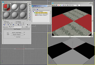
The scenario is a tile floor with solid red tiles alternating with marble pattern tiles and can be accessed by downloading Tile_viz4.max. (Download zip file at end of article) The red color will be set as the Diffuse and Ambient Color swatches of the material. A Mask map is applied to the Diffuse Color slot and is composed of a Perlin Marble map and a Checker mask. The white areas of the Checker mask are opaque and show the marble map. The black areas of the Checker mask are transparent and reveal the underlying solid red Diffuse Color. See Figure 1.


Figure 1: The Material Editor shows a Mask map in Diffuse Color slot that contains a map and a mask. The viewport and rendered image show the effect of black and white masking of the map. Perlin Marble shows in the white areas and diffuse red shows in black areas.


This example shows how the process works in a Diffuse Color example. In the next example I use a Mask map in conjunction with a Raytrace reflection map on a tile floor that can be found in Wall_viz4.max. The scenario here is a ceramic tile floor with Brick maps defining the color and the bump pattern and a Raytrace map that causes the material to reflect its surroundings.

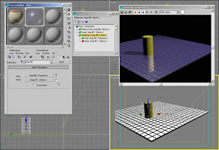
In the Mask map of the Reflection slot I have disabled the Bricks mask by unchecking it in the Mask Parameters rollout causing the reflection to be the same for both the tiles and grout. See Figure 2.


Figure 2: The mask of the floor tile Reflection slot has been disabled and you can see the reflection of the cylinder is the same in the grout and tile.


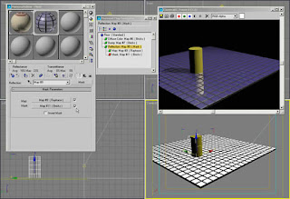
By applying the same Brick map I used in the Bump slot of the material to a Mask map with a Raytrace map, the reflections only occur in the white areas of the mask. See Figure 3


Figure 3: Enabling the Bricks mask reveals reflections in the tile areas but not in the grout areas for a more convincing floor material.


Masking at the material component level offers a lot of possibilities for experimentation. The same Reflection masking as above could be used with Raytrace and a Noise mask to give the illusions of puddles on a road surface. A combination of Bricks map in the Bump slot with a Gradient Ramp mask could create the illusion of a knurled surface on a tool handle. Use your imagination and experiment.

Masking at the material level

Masking at the material level functions the same as at the map level but increases the control another notch. Each material can have widely varying attributes like color, shininess, and bumps, each revealed or hidden by the mask. In the example here I’ll use the Blend material with the optional mask.

The scenario will be a wall that needs a combination of brick and stucco. As in most projects the exact material placement will be held in secret by the designer right up to the last minute of the deadline. I want to be able to make last minute changes quickly and easily. This is also using the file Wall_viz4.max. (Download zip file at end of article)

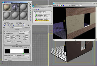
Blend material with masking allows us to do this nicely. I create the Blend material with a Brick and a Stucco material, each with different patterns, colors, and bumps. I’ll use a Gradient Ramp mask that has been adjusted for solid bands of black and white to reveal the two materials exactly where I want them on the model.

This wall example also illustrates a powerful feature of max and VIZ called Map Channels. Because the patterns of the brick, the stucco, and the mask repeat differently over the wall surface I needed different mapping coordinates for each map. The wall has three UVW Map modifiers each set to a different Map Channel. The Gradient Ramp mask is set to use Map Channel 1, the Brick map uses Map Channel 2, and the Stucco map uses Map Channel 3 so that each pattern may be adjusted independently. The Map Channel in the UVW Map must match the Explicit Map Channel setting of the map in the Material Editor.

The Gradient Ramp map has been rotated in the W axis in the Coordinates rollout for proper orientation on the wall. An alternative would be to rotate the UVW Map modifier Gizmo.

Figure 4 shows the Gradient Ramp map and the rendered image shows the result of the masking. Each material has it’s own color and bump information.


Figure 5: By adjusting the position of the flags in the Gradient Ramp map used as the mask, you can quickly reposition the location of the materials.


This same wall material could have been used with a Noise map to simulate a stucco wall with sections of plaster fallen off to reveal bricks below. You could also create the illusion of rust coming through a metal panel or grassy areas with patches of rock and dirt.

Animated masks

Masks do not have to be static images or maps. Interesting effects can be created by using animated masks in the form of avi or mov files or as sequentially number still images. You might say that it sounds logical, but you don’t have a 2D animation program to create the animated maps. Don’t fear, it is easy to create animated masks in 3ds max or Autodesk VIZ.

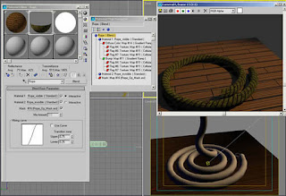
In the file called Rope_viz4.max (Download zip file at end of article) is a section of coiled rope made by lofting a circle around a helix and applying a material to it. The task at hand is to make the rope disappear over time, not all at once, but from one end to the other.

The solution here is to use a Blend material and a mask again. In the Blend material is a rope material and a material that is completely invisible. The opacity and glossiness of the material have been set to 0. It is important to set the glossiness to 0 to avoid a highlight on the invisible portion of the rope.

The mask is created in VIZ 4 by assigning a pure white material to a flat plane and animating the plane moving from just off screen to filling the viewport of a camera view. In this case it is Camera02. The animation was rendered as an avi file and used in the Mask slot of the Blend material.

Figure 6 shows the Blend material level in Material Editor and the result of rendering frame 15 of 30 frames. Half the rope that you see in the Camera01 viewport is invisible in the rendered image. See Figure 6.


Figure 6


The same technique could have been used to reveal a shiny new material under an old crusty material over time or to make a surface appear to bubble from the heat by revealing the base material with same material with a bump map added.

Note that it is important in this case that the rope be created in max or VIZ by lofting. Lofted objects are the only objects that generate mapping coordinates that allow the patterns to follow the curvature of the objects. For example the rope material and the mask both follow the rope as it winds upward.

Alpha channel and masking

You will often hear the term Alpha Channel in conjunction with maps in max or VIZ. It refers to information that is stored in certain bitmaps that determine transparency. The most popular files types with alpha channels are tga, tif, and png.

Computer generated images are displayed in pixels, either on screen or when printed. Since the early days of computer graphics anti-aliasing has been used to smooth diagonal lines and edges caused by stair-stepping across squarish pixels.

Anti-aliasing is done by blending the pixels at the edges of contrasting colors to make the edge appear smoother. If a red diagonal line is applied to a yellow background then some pixels are quite red with a little yellow, some are half red, half yellow, and others are quite yellow with a little red. This smooths the transition when seen from a distance.

However, if the red line is lifted from the yellow background and composited onto a blue background the yellow remnants look terrible and are worse than no anti-aliasing. 32 bit files or files with 24 bits of color and 8 bits of alpha channel use transparency pixels instead of the background color to create the anti-aliasing effect. Now when the red line with varying transparent pixels are composited to another background there is no problem and everything has clean edges that appear smooth.

Max and VIZ both can take advantage of files with Alpha Channel in the masks for a cleaner blend at either the map or the material level. Workings on the examples in this column don’t require Alpha Channel to work, but keep it in mind if you are experiencing problems with detailed masks in your explorations.

Summary

Masking gives you control of materials you never thought possible. The concept and application are simple at its base level, but by combining masks at different levels you can create materials that are complex yet easily edited.

As a personal plug, if you are a 3ds max 5 user, my new 3ds max 5 Fundamentals book by New Riders Publishing is set to appear in late October or early November. It is somewhat different than my previous fundamentals book in that I focus on the many new max 5 features in a series of exercises that take you from a medieval village to building a personal transporter, and a trip to the fortune tellers. The exercises are designed to be an interesting and informative way to learn uses for max 5 features from modeling, to materials and radiosity lighting, to collision detection and scene editing and compositing.

In any case, good luck and have fun.

Ted


Read More......

Tuesday, January 29, 2008

RUNNING WATER

by Ted Boardman

You’ll often hear it said that you need 3ds max to create running water effects with Particle Systems and it can’t be done in VIZ. Well, true enough that VIZ doesn’t have Particle Systems, but that’s only one type of running water and the method I’ll cover in this months column is valid in any version of both max and VIZ.

The process is quite simple once you have the speed and scale of the animated map for the water worked out. There may be some formula that could be devised to figure the size of the maps and the motion necessary to produce the desired results, but I have found that just doing a few test renders for both the map and the final water material is the best method. Because the Noise map used is a Procedural map it has no real-world “size” and the dimensions of the surface Noise is mapped to and the size of the water surface the material is applied to a little experimentation is necessary.


This won’t be a step-by-step tutorial this month, but I’ll walk you through the process I used to Model the landscape and to set up the material for both the landscape and the water and will encourage you to use my example to create a scene of your own.


Figure 1 shows a still image from an animation of water running through a ravine on a sloping landscape.


The Landscape

The first thing to look at is the landscape itself. The modeling is done with the same method I covered in last month’s column. A Gradient Ramp map is used in the Displacement slot of one part of landscape material.

The whole material is a Blend material so that a Falloff mask can be used to reveal dirt on the sides of the ravine and grass on the flat surfaces of the landscape. This is the same method used for the snowy mountain with some adjustments for color and bump mapping. See Figure 2 for the Gradient Ramp displacement map on the left, the result of that map in the center, and the structure of the material in the Navigator on the right.


Figure 2: Gradient Ramp Displacement map settings and the Landscape material hierarchy in the Navigator.


The color and bump patterns of the landscape material are simply combinations of Smoke, Noise, and Speckle maps to provide a variety of shades and textures to enhance the randomness of natural materials. Be sure to open the viz file and experiment with the materials to get the look you want in your scenes and to see the settings in the Displacement mapping that will help optimize the landscape mesh.

The Water

What this column will focus more attention on is the water material itself. It’s really made up of two processes. One mesh and material are used to generate the animated maps that create the illusion of movement for the water in the ravine.

In the right-hand Top viewport of my Flowing_water_viz4. max file, I have created a Plane primitive object off to the left of the landscape. I then applied a material called Water map that contains a Noise map in the Self-illumination slot. See Figure 3 for the Noise settings and the resulting map.


Figure 3: Noise map settings for the Self-illumination slot of the Water map material that is applied to a flat plane.


TIP: you can view a large version of any map by toggling the Show End Result button in the Material Editor, then double-clicking on the Sample Window to show an enlarged window.

The Noise map is used in the Self-illumination slot because we want to generate a black and white animation to use as a map in the water material and do not want to have to adjust the lighting in the scene for this object. A black and white map causes the white areas to be fully self-illuminated and the black areas to have no self-illumination to render correctly with no variations caused by the scene lighting.

This new material is applied to the flat plane. In a Top viewport, zoom in so that an area of the flat plane fills the viewport. Right-clicking the viewport label and checking the Show Safe Frame option will ensure that what you see in the viewport is the area that will be rendered.

Now you can animate the flat plane moving past the viewport by turning on the Animate button, going to the last frame in the Time Slider, and moving the plane. This will cause the pattern to move as you render.

There is some trial and error required to get the size of the pattern and the movement of the plane to match the water flow that you want in your scene. I haven’t devised a reliable set of rules that states, “if you do X, you will always get Y” as a result. The overall size of the actual water surface object in the landscape, the amount of ripple you want, and the apparent speed of the current are all variables that come into play. I recommend you test with a short 15 frame example with only the flat plane and the water surface object visible until you get the speed the way you want, then render the whole sequence to be more efficient.

In the example file for this column I rendered the full 100 frames from the left-hand Top viewport (there are two Top viewports). I chose to the render images as individual PNG files at 24-bit color with Alpha channel. You could render as an AVI or MOV file as well, but you will get better results using Alpha channel when possible, especially for bump maps and masks. PNG files are highly compressed and load fairly quickly. The name of the rendered file was water.png and because it is 100 frames the individual files are actually named water0000.png through water0100.png.

Again, the Water surface material is a Blend material with a mask to vary the color and shininess for a more random look. Figure 4 shows the Navigator so you can see where the PNG files were used; as Bump and Mask maps.


Figure 4: The Water surface material is a Blend material that uses the rendered sequence of images as Bump and Mask maps.


TIP: the animated map is actually an ifl file that shows in the map slot. This file is automatically generated when you use one map of a sequentially numbered set of maps and check the Sequence option in the dialog. The ifl file is simply an ascii text file that lists all the files in the sequence. Max and VIZ then call the correct image for each new frame in the final animation.

The transparency of the water is not created by setting the Opacity lower, but by using a Thin Wall Refraction map in the Refraction slot. This automatically makes the material fully transparent and distorts surfaces behind the water surface. I then set the Refraction Amount in the Maps rollout to around 90 to reduce the transparency somewhat and allow the colors in the Diffuse slot to show.

Another important factor for water is to set the Specular level fairly high and to use a Falloff map in the Glossiness slot. This Falloff map has its Mix Curve adjusted to give hard-edged Specular highlights on the water surface. See Figure 5 for the Falloff Mix Curve. The Mix Curve points can be adjusted for different viewing angles and lighting scenarios.


Figure 5: Falloff map with Mix Curve to cause hard-edged Specular highlights on the water surface when the Specular level is set high.


Try a few variations of the materials and lighting in this example scene then try making your own from scratch.

The modeling of the water surface can also be important to the end result. As with any models, you want to be as efficient as possible and still get the amount of detail you need. I recommend lofting the water surfaces for several reasons; you can adjust the density of the mesh (face count) easily with Path and Shape Steps and, more importantly, lofted objects will generate mapping coordinates that allow the material to follow the curvature of the loft path. This would be very important for water that flowed around corners or spilled from a fountain spigot.

TIP: if the water map appears to be flowing in the wrong direction of the lofted surface you can edit the loft path at sub-object Vertex level and change the First Vertex to the opposite end of the path or at Spline sub-object level with the Reverse button.

You can also change the map itself by adjusting the W angle rotation in the Coordinates rollout.

In this example the water surface is a short Line shape lofted along a longer Line path that has been moved into position in the ravine. If, by chance, the lofted surface is not showing when you loft your own example it may be because the Face Normals are pointing in the wrong direction. Changing the First Vertex position on the shape Line will flip the normals or you can apply a Normal modifier to the loft object.

In this case I used a Noise modifier on the lofted surface to give it some extra bumpiness than that achieved with the Bump maps alone.

Enhancing the Contrast

Our perception of both water and glass (very similar properties for both) are often enhanced by increasing the sharpness and contrast of the rendered scene. I personally like contrasty images anyway so it works well for me.

One step you can try for overall sharpness is to change the filter that is used during rendering. In Figure 6 you can see that I have changed the filter from the default Area filter to a Catmull-Rom filter that gives sharper edges of dark and light areas. Another option would be to try the Mitchel-Netravali filter.


Figure 6: Changing the filter in the Render dialog from Area to Catmull-Rom can enhance the apparent contrast of water or glass.


While the filter affects the image when rendered another option that is seldom used is the Contrast adjustment on the lights themselves. In the Modify panel, Advanced Effects rollout, (see Figure 7) for a light you can adjust the Contrast setting to create radical changes in the rendered image. It may be helpful to light the water with a light that Excludes all other objects if you don’t want to increase the overall contrast in the scene.


Figure 7: Each light has a Contrast setting in the Advanced Effects rollout that can dramatically affect the lighting.


While you’re in the Advanced Effects rollout, try adjusting the Soften Diffuse Edge setting for scenes that have curved shaded surfaces. This setting will harden or soften the edge at the transition of lit to shaded areas and can be used to adjust the Specular highlights of glossy surfaces.

TIP: Use RAM Player to compare two images side by side when making adjustments to important materials and lighting setups.

Summary
Water is one of the most dynamic and difficult surfaces to render. This column gives you a possible starting point from which to experiment in your own scenes. Keep in mind that the position and quality of the lighting can make or break the appearance of materials like water and glass so always adjust each as you fine-tune your renderings.

Make sure that you take the time to look closely at water and glass in the real world in all lighting conditions so you can visualize what you must to in max and viz to achieve a certain look. You might even think about how an oil painter might approach the look and attack the problem from that perspective first.

In any case, good luck and have fun.

Ted

Read More......